
Choose repeatability after the view is known.
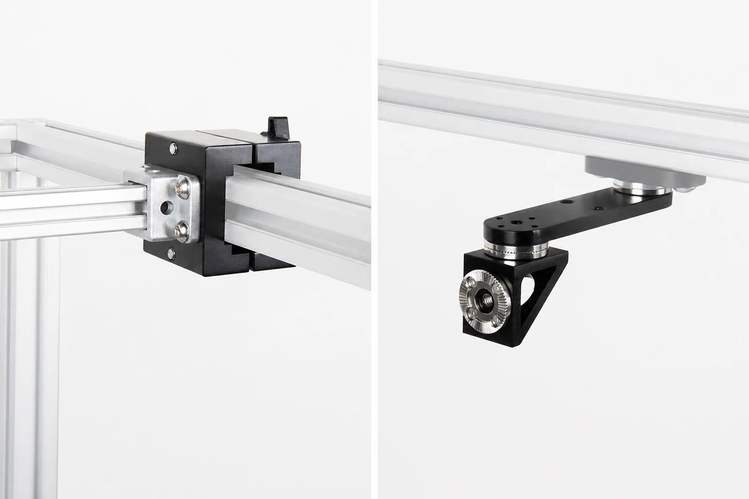
Flexible arms are excellent for finding a view. Rosette mounts are better when that proven position must become a defined machine build.
Each joint uses interlocking teeth to select a discrete angle before the center fastener is tightened. If a device is removed for maintenance, the installer can return it to the same tooth position instead of aiming it again by eye.
The benefit is not “more adjustment.” It is more controlled adjustment: a shorter mounting path, fewer drifting friction joints, and geometry that can be recorded for assembly and service.
Advantage: indexed return
Toothed positions give technicians a repeatable angular reference after loosening and retightening a joint.
Advantage: modular stiffness
Use only the turn and extension needed. Shorter chains reduce leverage and remove unnecessary joints.
Trade-off: stepped aim
Rosette teeth provide discrete positions, not continuous freehand fine aim. Coarse placement at the extrusion still matters.
Build from the machine frame to the device.
Anchor. Turn. Reach. Hold.
3030 / 4040 extrusion → E3040 rosette interface → optional 90° Connector → optional 100, 150, or 200 mm extension → device holder → payload.
The frame-side interface anchors the system. The 90° Connector changes direction. The extension establishes working distance. The final holder matches the camera, light, sensor, or other device.
“Optional” is important: skip the connector or arm if the payload can sit closer to the frame.
Start with geometry, then select the minimum chain.
| Part | What it does | Choose it when | Do not add it when |
|---|---|---|---|
| E3040 rosette interface | Anchors the indexed path to 3030 / 4040 extrusion. | You are starting a rosette chain from an existing machine frame. | Another validated rosette interface already anchors the chain. |
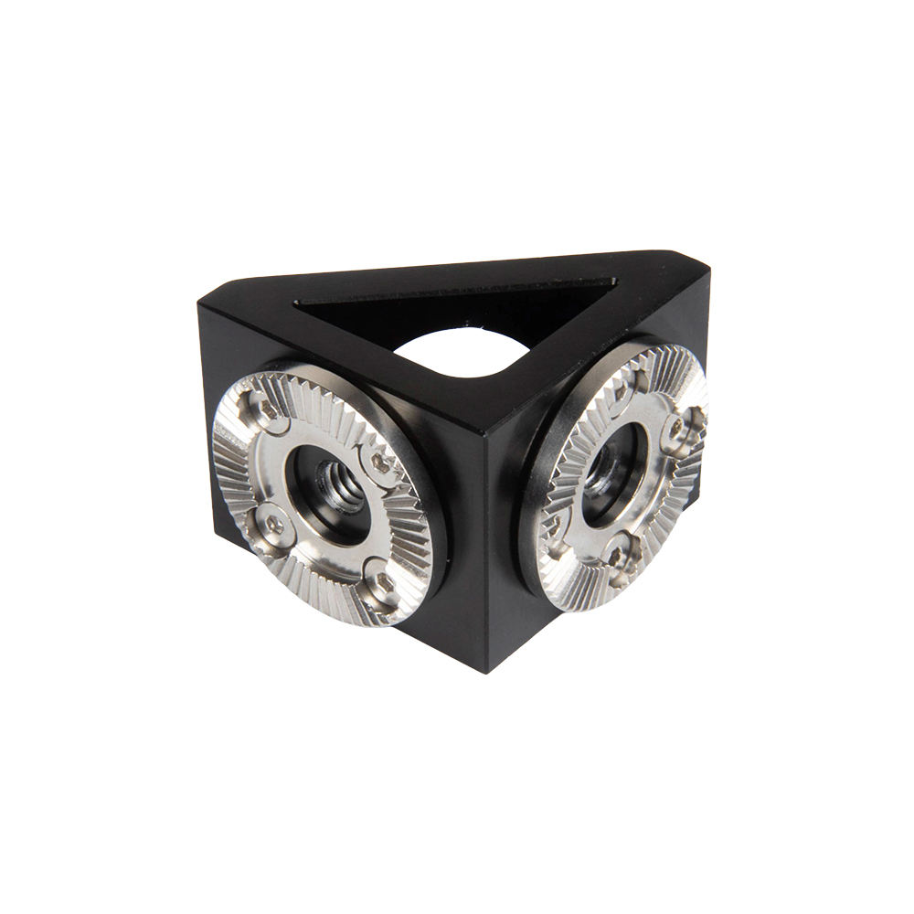
| Rosette 90° Connector | Turns the mounting path through a rigid right-angle corner. | The device must face inward from a post, hang below a crossbar, or turn away from the extrusion face. | A straight frame-side connection already points the device correctly. |
| Rosette extension arm | Adds a measured straight offset while keeping rosette interfaces at the ends. | The payload cannot reach its working position directly from the frame-side node. | The device holder can connect close to the frame. |
| Device holder | Matches the indexed chain to the payload-side hole pattern, thread, bore, or plate. | The exact camera, light, sensor, or accessory interface is confirmed. | The payload fit and anti-rotation requirement are still unknown. |
| Extension | Best reason to choose it | Advantage | Disadvantage |
|---|---|---|---|
| 100 mm / 10 cm | It reaches the required position without crowding the connector or camera. | Shortest standard offset and normally the lowest leverage. Preferred starting point. | May not clear deep guards, conveyor edges, or large connectors. |
| 150 mm / 15 cm | 100 mm is too short, but the layout does not require maximum reach. | Balanced general-purpose offset. | More leverage and cable exposure than the 100 mm arm. |
| 200 mm / 20 cm | The payload must reach farther into the inspection area or around an obstruction. | Longest standard coverage. | Greatest leverage in the ladder; payload, vibration, and cable pull need closer review. |
Finish the rosette path with the holder the payload needs.
Machine-vision camera plate
Use a camera-specific or pattern-confirmed plate when orientation must not rotate around a single screw. Confirm the exact camera model and hole spacing.
1/4 inch-20 device
The center thread on a compatible extension can carry a compact camera, light, or accessory directly. Add anti-rotation support when image orientation matters.
Ring or bar light holder
Match the final holder to the light body and mounting holes so illumination angle returns with the indexed joint.
M18 sensor holder
A dedicated bore lets the sensor barrel nuts secure an M18 sensor while the rosette controls aim.
Measure the successful trial before replacing it.
1. Find the view
Use Super Knuckle, OmniGrip, or Vision Arm to test working distance, field of view, illumination, connector access, and cable direction.
2. Record the geometry
Measure the frame landing point, straight offset, direction change, payload orientation, and required maintenance clearance.
3. Rebuild and validate
Use the fewest rosette parts that reproduce the view, then check fasteners, image stability, vibration, cable strain relief, guarding, and service access on the real machine.
Choose reach and direction separately.
Rosette 90° Connector
Turns an indexed mounting path through a rigid right-angle corner.
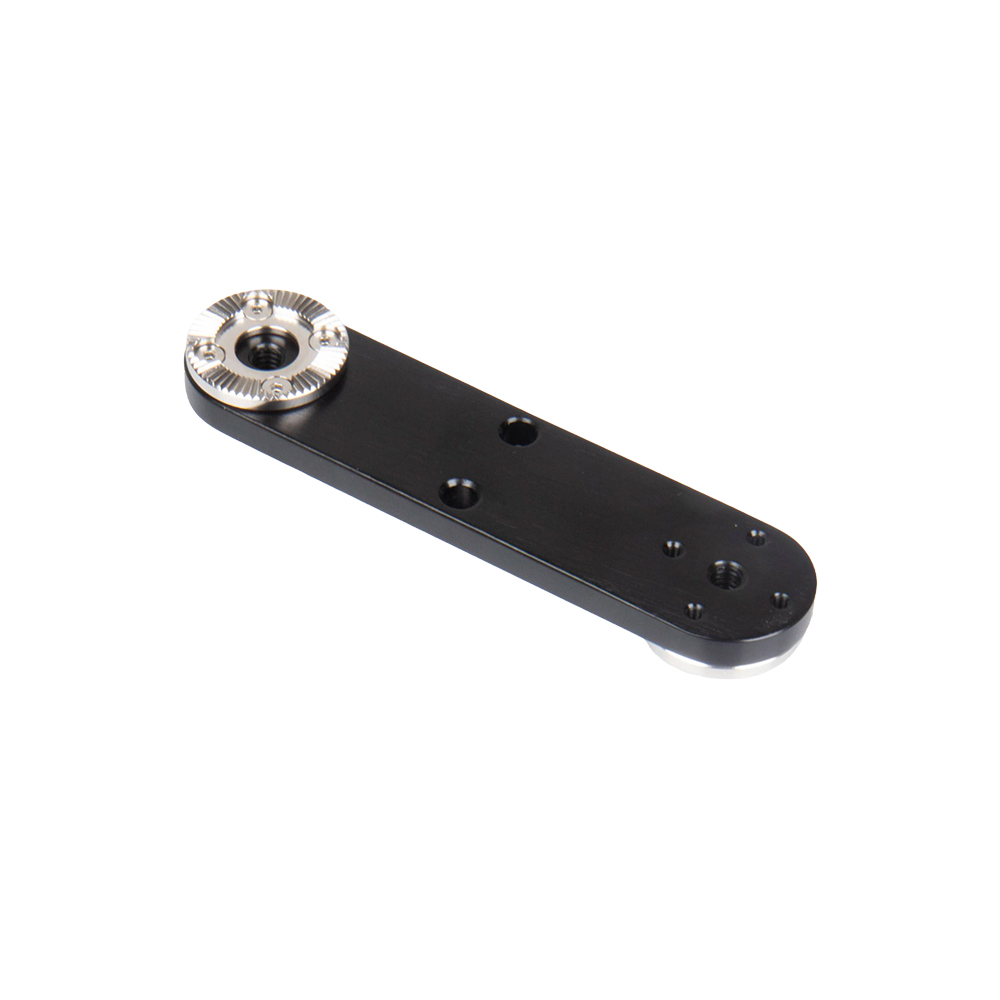
Rosette Arm 100 mm
Preferred when the shortest standard extension reaches.
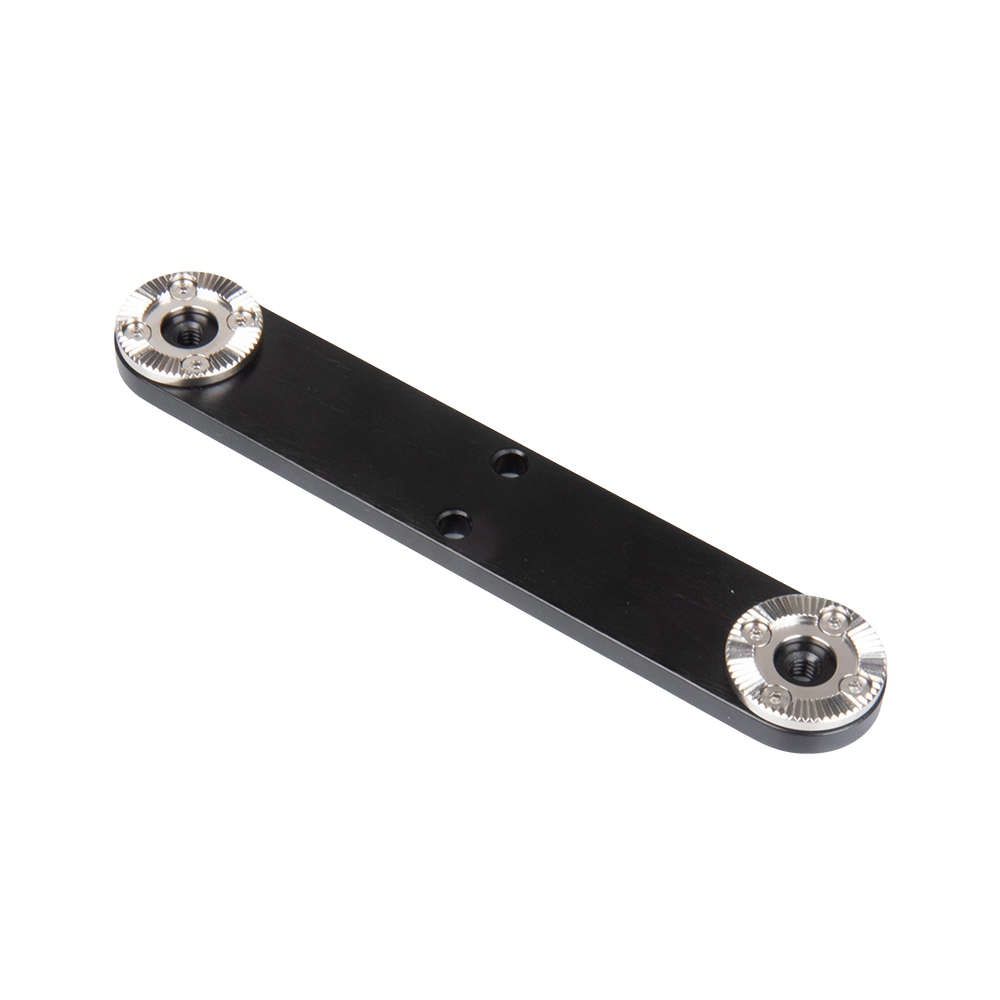
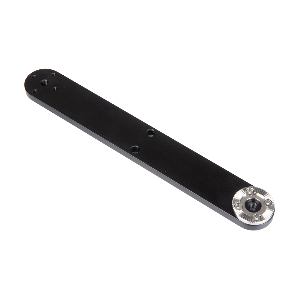
Rosette Arm 200 mm
Maximum standard offset, with the greatest leverage to manage.
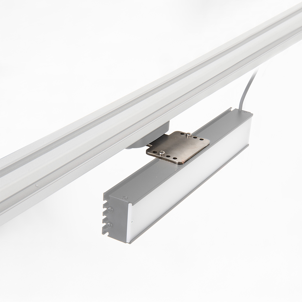
Rosette Bar Light Mount
Locks a compatible bar light at a repeatable indexed angle.
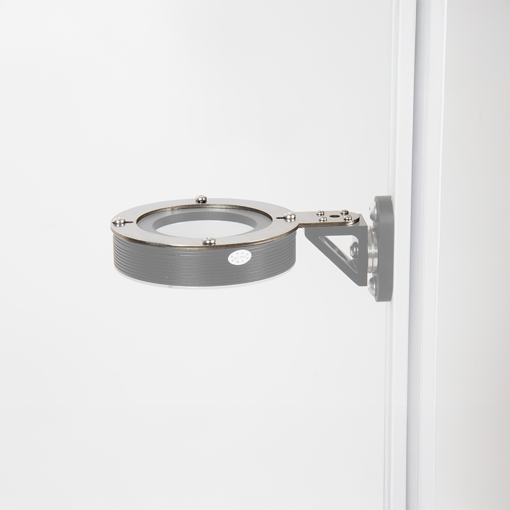
90 mm Ring Light Mount
Supports a larger ring light on a repeatable indexed joint.
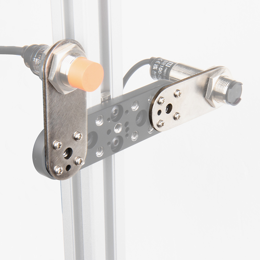
M18 Rosette Sensor Mount
Uses the sensor barrel nuts for a locked, repeatable aim.
The Square Tube Coupler solves a different problem.
Choose the Square Tube Coupler when the main need is a clamp-on structural offset from a 30 × 30 or 40 × 40 square extrusion member.
Its 20 × 20 mm extrusion set creates a light secondary rail for mounting devices farther from the main frame. Its VESA set creates a dedicated industrial-monitor path. These are useful companions to SightLink, but the coupler is not automatically a stage in every Rosette Link build.
Indexed does not mean automatically production-approved.
Validate the complete chain
Working behavior depends on arm length, payload center of gravity, orientation, fasteners, frame stiffness, cable pull, vibration, and repeated service.
Control cable forces
Secure cables separately near the device. A stiff mount can still lose image position when an unmanaged cable loads the final joint.
Confirm anti-rotation
A single 1/4 inch-20 screw may allow a camera or sensor to rotate. Use a pattern-confirmed plate or another anti-rotation feature when orientation matters.
Asked before ordering.
Is a rosette mount continuously adjustable?
No. The teeth lock into discrete indexed positions. That is what makes angular return more repeatable, but it is less freeform than a ball joint or articulated arm.
Do I always need the 90° Connector?
No. Use it only when the path must turn away from the frame face or around a corner. A direct stack with fewer parts is preferable when it already gives the correct direction.
Can the extension arm mount directly to extrusion?
The extension arms include center mounting holes intended for M6 fasteners and T-nuts, allowing a flat bolted route on compatible extrusion. Confirm the exact slot hardware and layout for your frame.
Which information should I send KUPO?
Send a frame photo, extrusion size and landing face, measured offset and direction, device model and weight, mounting pattern, cable exit, vibration condition, guard clearance, maintenance access, and image-position tolerance.