
Indexed orientation
Two mating tooth faces define a discrete angular position and resist rotation at the joint.
The KR-Interface rosette architecture turns a proven camera, light, or sensor position into a modular chain of indexed connectors, extension arms, and device holders on compatible extrusion.
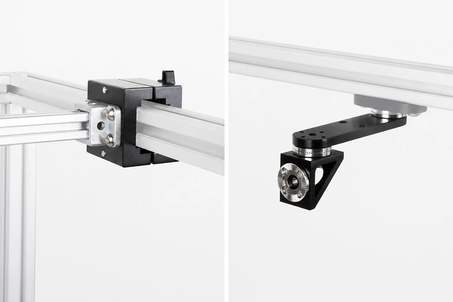
The rosette teeth provide indexed anti-rotation between modules, helping a removed component return to a known tooth position rather than relying on friction alone.
Two mating tooth faces define a discrete angular position and resist rotation at the joint.
Straight extension arms and a 90-degree connector build the required offset without one welded bracket.
Camera, light, or sensor holders remain identifiable modules that can be reviewed and replaced separately.
Keep the support path short: start at the compatible frame-side node, add only the required turn and offset, then finish at the correct device holder.
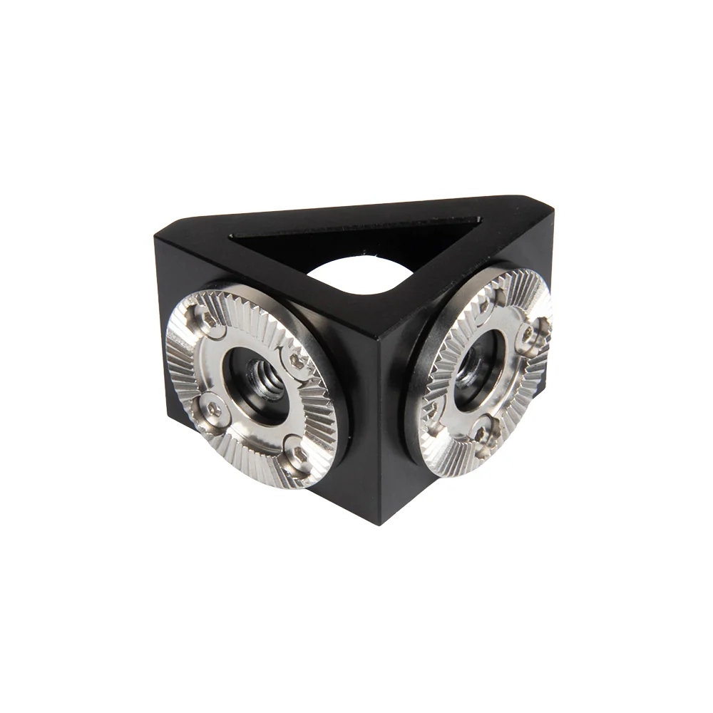
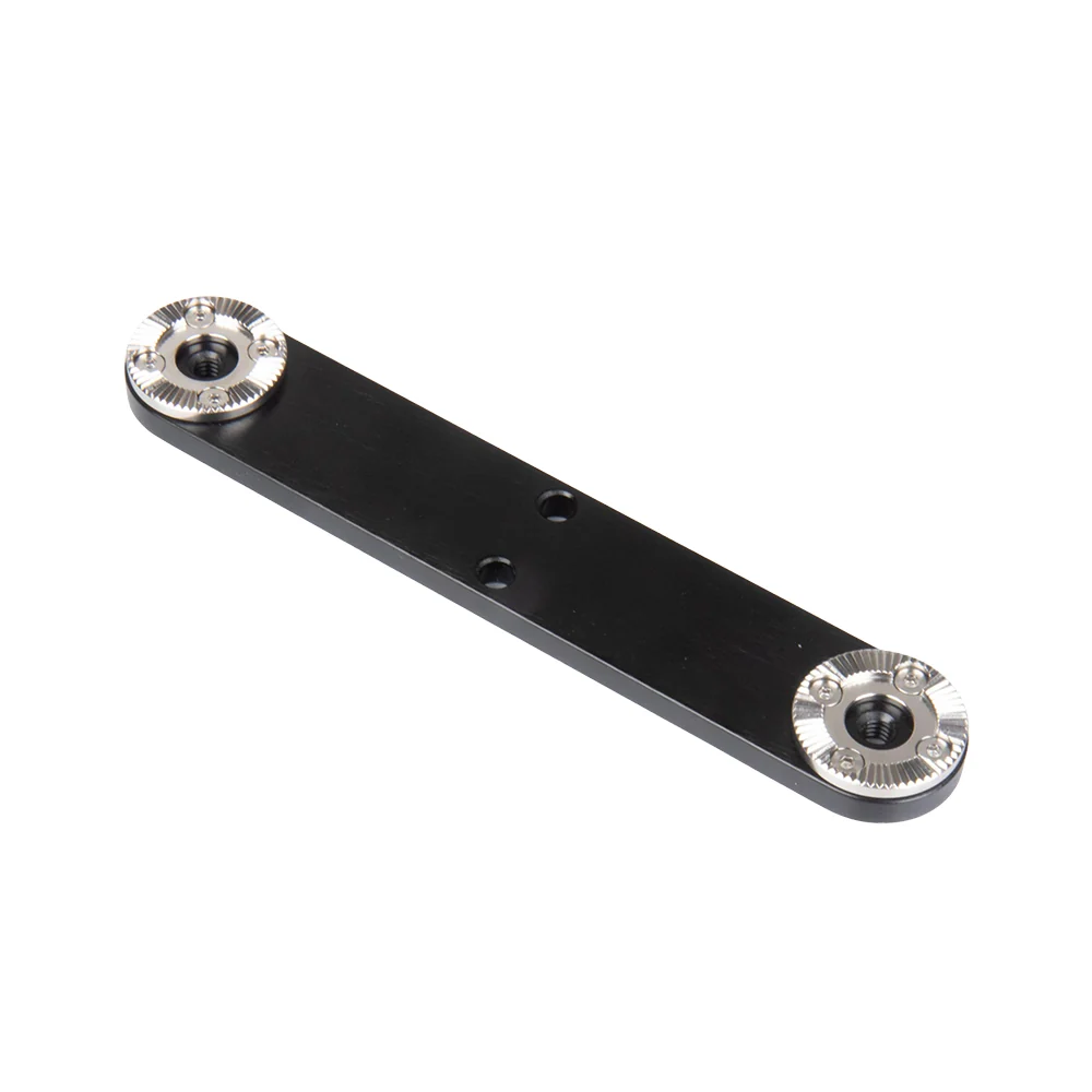
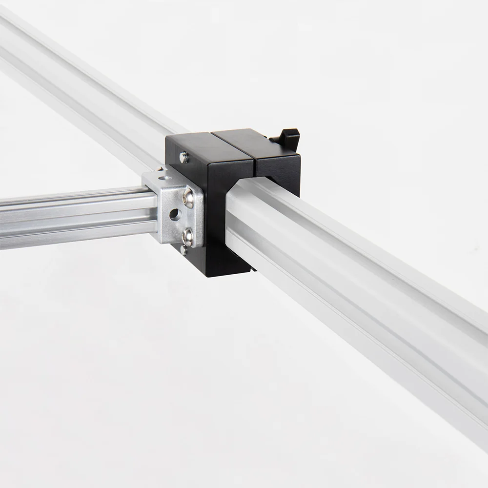
Each product has one structural role: the connector turns the path, the arm creates offset, and the holder interfaces with the actual device.
| Module | Role | Important boundary |
|---|---|---|
| KR-E3040-RS90 | Creates a fixed 90-degree change of plane between compatible rosette modules. | It is a connector, not an extension arm or payload holder. |
| KR-E3040-RSA10 / 15 / 20 | Provides 100, 150, or 200 mm nominal rosette-center offset. | Choose the shortest length that reaches. |
| VisionHolder / SensorHolder | Connects the support chain to a ring light, bar light, or M18 sensor. | Confirm the actual device geometry before ordering. |
| KR-E3040-SQC01-EX20 | Creates an auxiliary 20 × 20 extrusion rail for downstream modules. | It is not a direct camera mount and remains provisional. |
A production-facing retrofit is released only after the complete chain is reviewed under the real payload, reach, vibration, cable, guarding, collision, and maintenance conditions.