
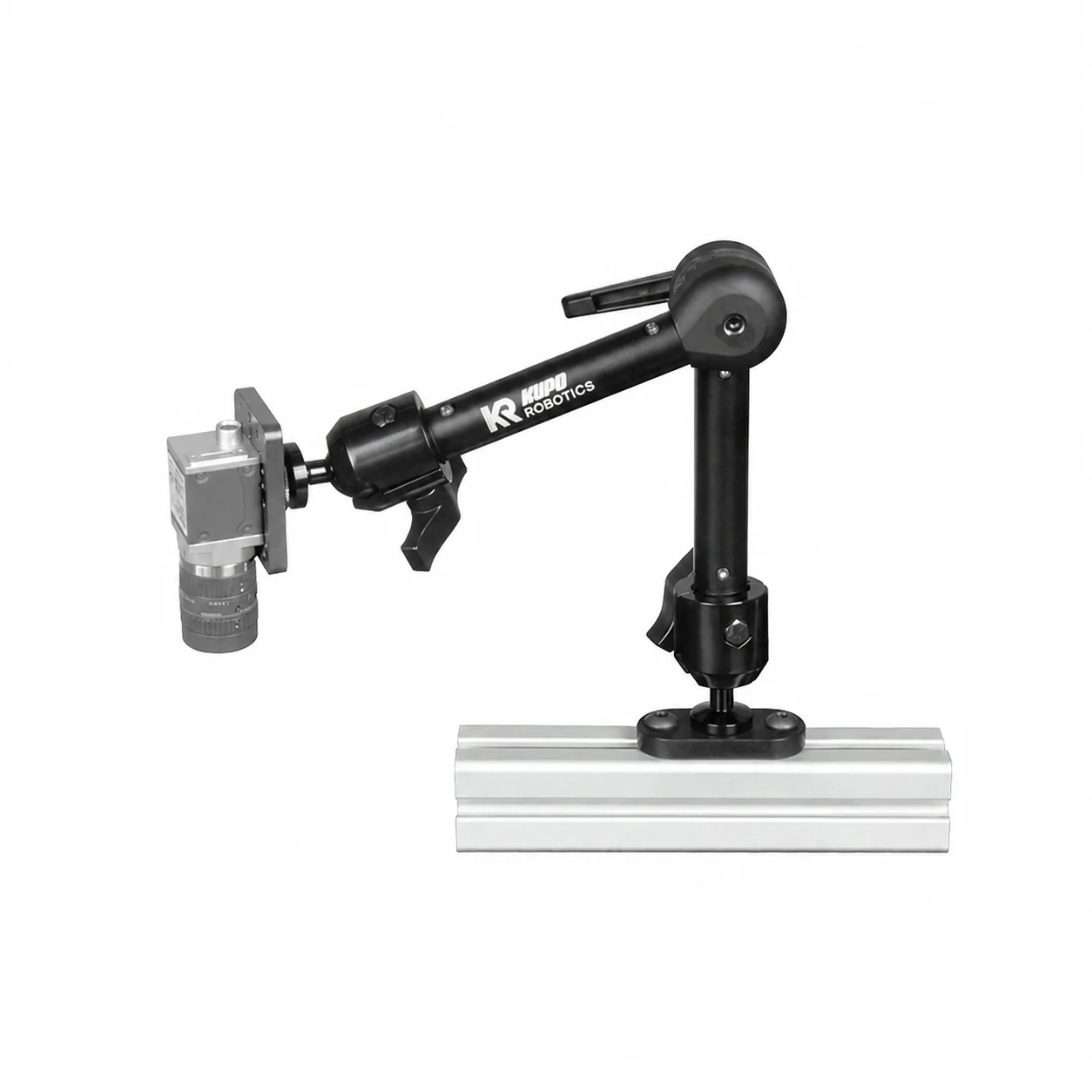
Machine-vision camera
Use a Q20M support only when the camera or adapter accepts a compatible 1/4"-20 male screw. Add an anti-rotation plate when orientation matters.
Start at the payload interface, confirm the device dimensions and cable direction, then choose the compatible arm, rosette chain, and parent structure that supports it.
The current 40-product draft supports camera-thread routes plus dedicated ring-light, bar-light, M18 sensor, and VESA monitor products.
Use a Q20M support only when the camera or adapter accepts a compatible 1/4"-20 male screw. Add an anti-rotation plate when orientation matters.
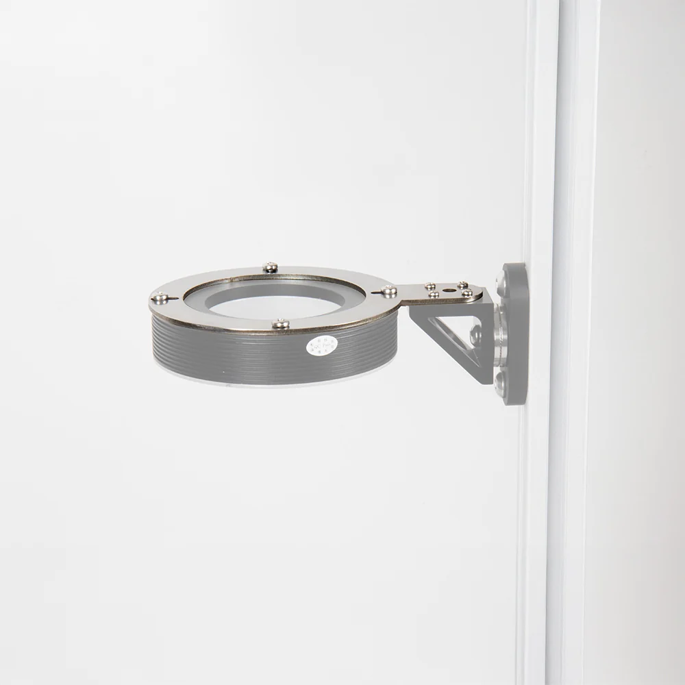
KR-VH-RL90 supports the current 90 mm VisionHolder route. Confirm the real light diameter, body profile, cable exit, and rosette-side connection.
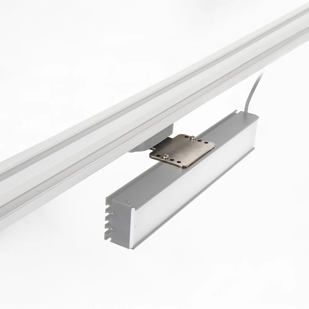
KR-VH-BL01 is the current bar-light holder route. Confirm the section geometry, clamp contact, cable direction, and required aiming angle.
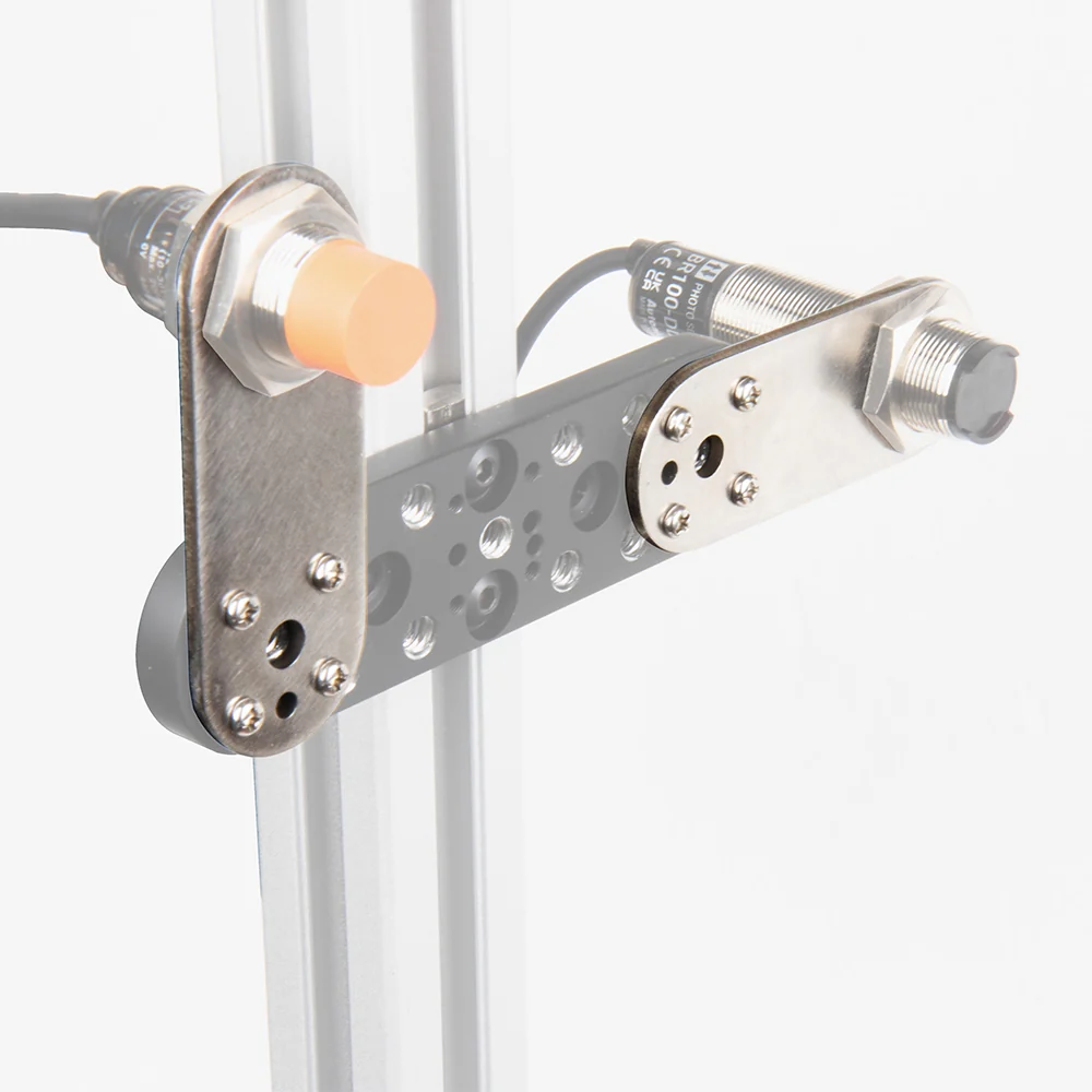
KR-SH18 is the current SensorHolder route for an M18-format sensor. Confirm barrel diameter, sensing direction, connector, and adjustment access.
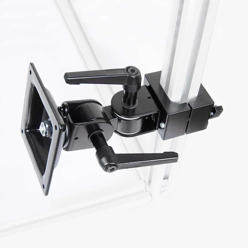
KR-E3040-SQC01-VESA is a dedicated VESA monitor mount for compatible extrusion. It is not a camera side-extension product.
Do not choose an arm from reach alone; confirm the payload interface and cable behavior before selecting adjustment style or parent structure.
| Step | Question | Decision created |
|---|---|---|
| 1. Device | What is the complete mass, center of gravity, thread, hole pattern, or holder geometry? | Defines the endpoint or adapter. |
| 2. Cable | Where does the connector exit, and what bend radius and strain relief are required? | Defines clearance and unplanned load. |
| 3. Position | What working distance, angle, offset, and service access must be preserved? | Defines reach and adjustment behavior. |
| 4. Structure | Is the parent a 16 mm VisionGrid frame or compatible extrusion? | Defines the family and base. |
| 5. Environment | Is this a lab trial, extrusion prototype, or production-facing retrofit? | Defines validation and final hardware expectations. |
A device holder may use the shared KR-Interface, but the supporting base must still match the actual 16 mm frame, 22 mm frame, 35 mm post, or extrusion structure.
Use VisionReach 16 bases only. Do not substitute the 22 mm or extrusion base.
Use a current E3040 positioning route after confirming the real profile, slot, and T-nut access.
Use the reviewed rosette chain after the geometry is frozen and the provisional hardware is released.
Other cameras, lights, sensors, controllers, cable accessories, or plates may be supported after their interface and geometry are reviewed.