Extrusion-cell prototyping

Prototype inside the real machine-cell envelope.

Use current SightLink E3040 positioning mounts on compatible extrusion to prove camera, light, sensor, cable, and operator-clearance geometry before a rigid production fixture is released.
Structure20 / 30 / 40 mm extrusion
Behavioradjust and prove
Outcomefrozen geometry
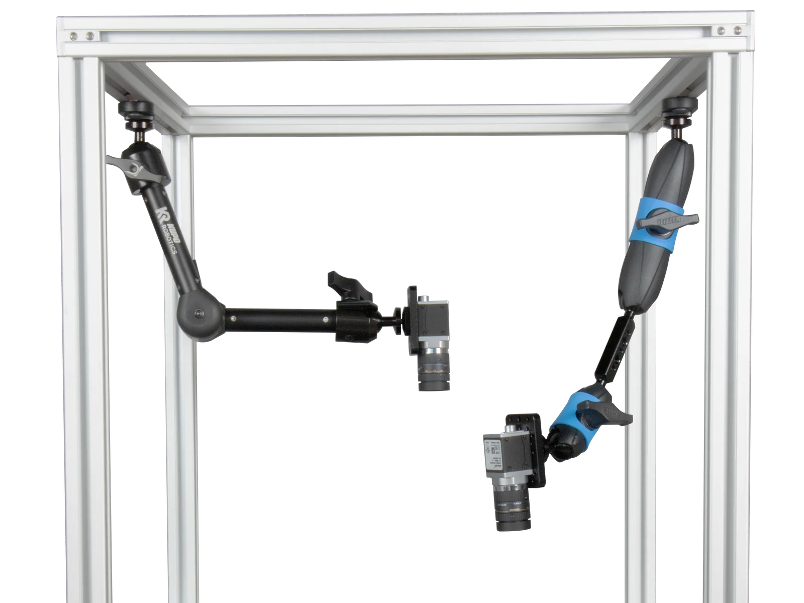
SightLink camera mounts positioned inside an aluminum-extrusion prototype cell
Prototype the inspection inside a realistic extrusion frame before production hardware is frozen.
Why extrusion

Test the constraints that a tabletop rig cannot show.

An extrusion prototype reveals the real camera offset, guard clearance, cable bend, operator access, and frame-face limits while the geometry can still change.

Machine envelope

Check where the camera and light can sit relative to doors, guards, conveyors, and moving equipment.

Service access

Prove that the device can be adjusted, cleaned, disconnected, and replaced with normal tools.

Cable behavior

Confirm connector projection, bend radius, strain relief, and whether the cable pulls the image out of position.

Current route

Use SightLink positioning arms to find the geometry.

Super Knuckle, Omni, and Vision Arm products are setup tools for proving position on compatible extrusion; they are not automatic production mounts.

Mounting behavior Current E3040 family Use it when
Fast freehand adjustment Super Knuckle 8 / 15 / 23 cm The camera or light needs frequent coarse and fine movement during trials.
Indexed discrete angle Omni 20 / 30 / 40 cm A toothed joint helps return to a previously tested angle.
Lower-profile direct thread Vision Arm 19 / 30 cm The device needs a slimmer support path and the clearance has been checked.
Compatibility: confirm the actual profile, slot standard, T-nut access, mounting face, and member orientation. Nominal extrusion size alone does not prove fit.
Selected products

Choose the adjustment behavior that fits the trial.

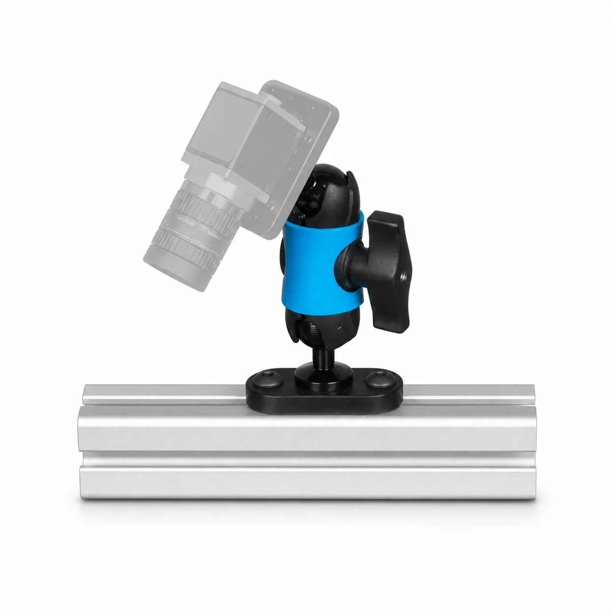
KR-E3040-SK08-Q20M SightLink E3040 Super Knuckle mount with illustrative camera
KR-E3040-SK08-Q20MFast close-in positioning during discovery.
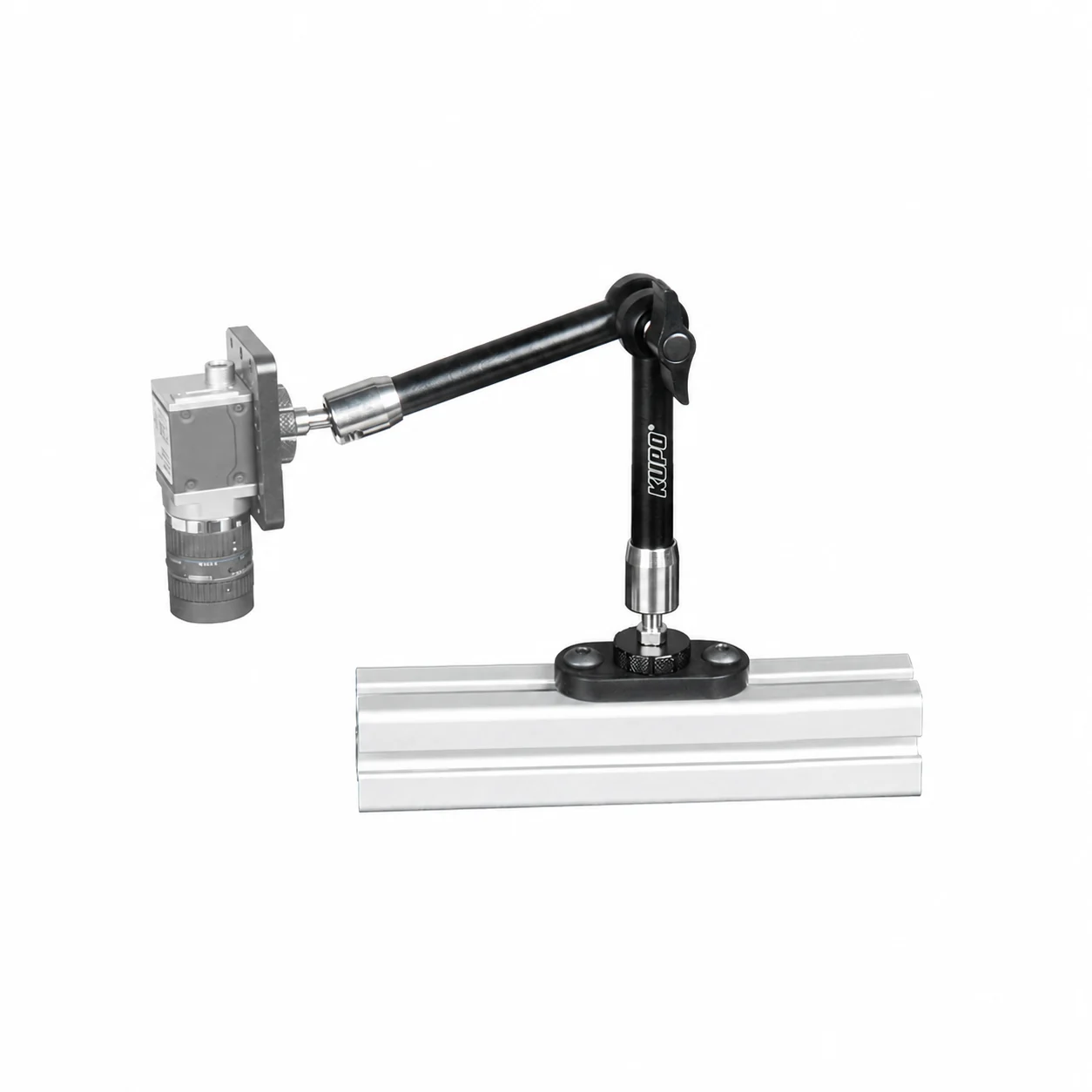
KR-E3040-OM20-Q20M SightLink E3040 Omni mount with illustrative camera
KR-E3040-OM20-Q20MIndexed angle trials on compatible extrusion.
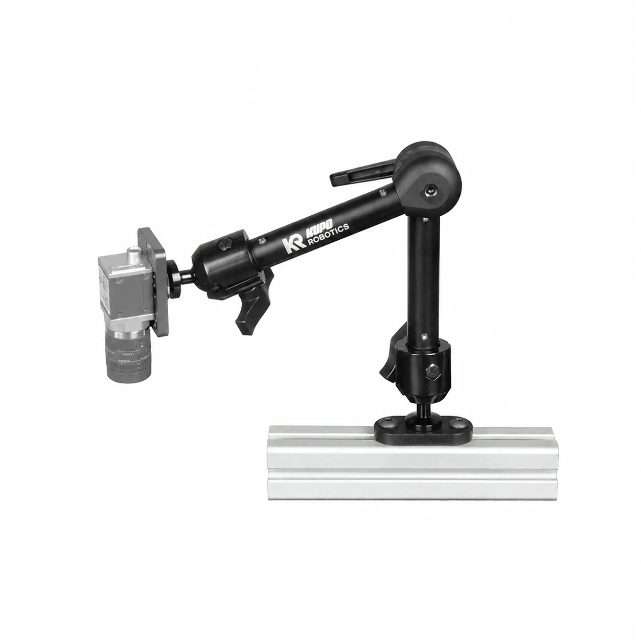
KR-E3040-VA19-Q20M SightLink E3040 Mini Vision Arm with illustrative camera
KR-E3040-VA19-Q20MA lower-profile direct-thread support route.
Prototype output

Record the geometry that the final fixture must preserve.

The useful output is not only a working image; it is a documented set of distances, angles, clearances, cable paths, and maintenance requirements.

  • Camera-to-sample working distance and viewing angle.
  • Light position, height, direction, and cable exit.
  • Device mass, center of gravity, adapter, and anti-rotation requirement.
  • Selected mounting face and required offset from the extrusion.
  • Guard, door, operator, cleaning, and tool-access clearances.
  • Vibration source and acceptable image-position tolerance.
Next step

Move from adjustable proof to reviewed production hardware.

When the geometry is frozen, retain the proven coordinates and evaluate an indexed KR-Interface or engineered rigid fixture for the final environment.

Production boundary: load, vibration, cable pull, guarding, collision risk, maintenance access, fastener retention, and image-position tolerance still require application review.
Related collections

Continue with the extrusion route.