
Fast freehand trials
Start with KR-VR16-SK08-Q20M when quick close-in adjustment is the main need.
VisionGrid 16 Compact gives integrators a repeatable 30 × 30 cm working area for finding camera position, light angle, working distance, and sample presentation before the final machine is designed.
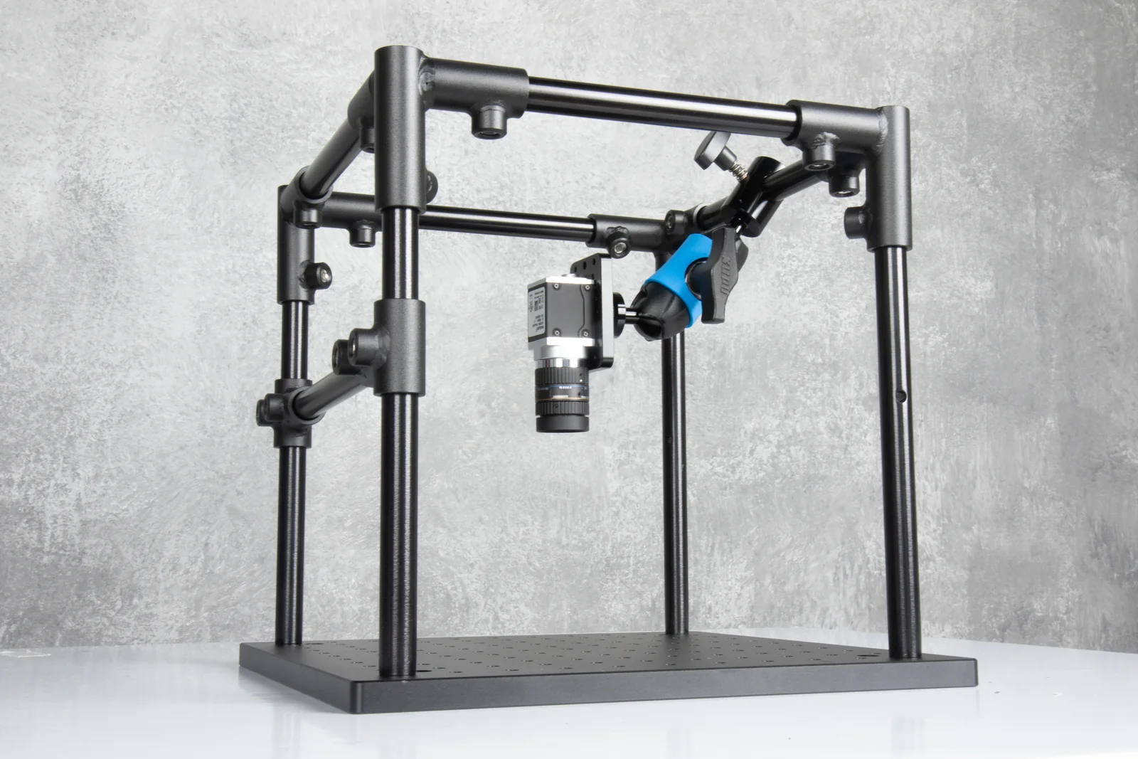
Choose the 16 mm compact route when the sample is small, bench space matters, and the camera or light still needs to move between trials.
The compact platform is the parent structure; every camera or accessory path must use a VisionReach 16 base rather than the incompatible 22 mm or extrusion families.
Start with KR-VR16-SK08-Q20M when quick close-in adjustment is the main need.
Start with KR-VR16-OM20-Q20M when returning to a discrete toothed angle is useful.
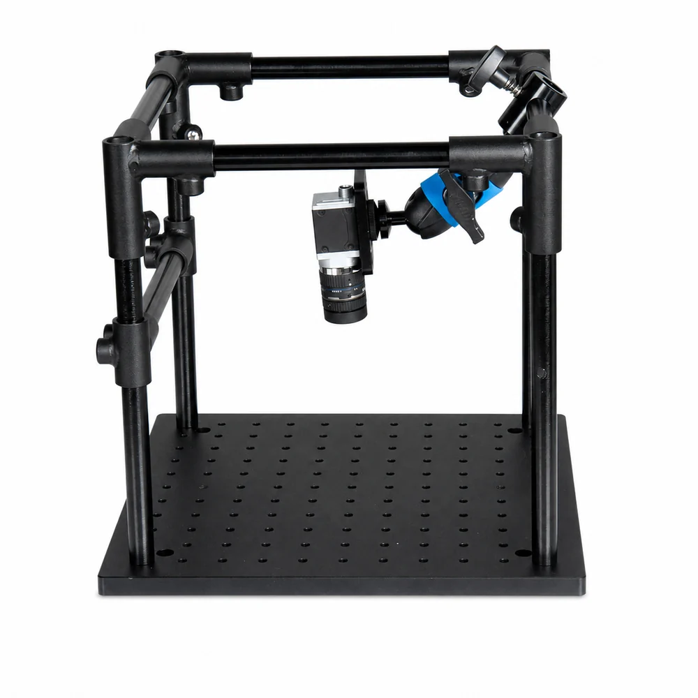
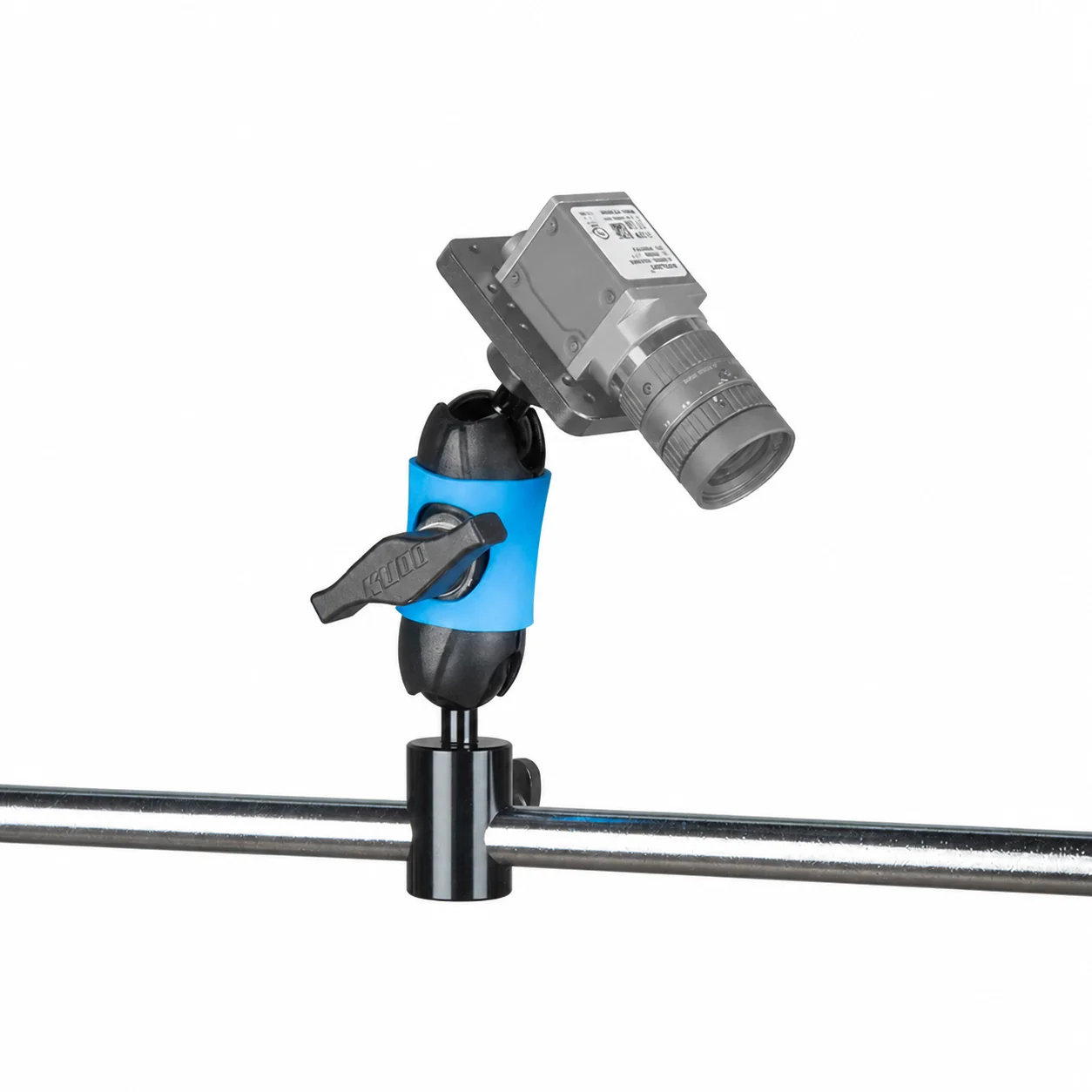
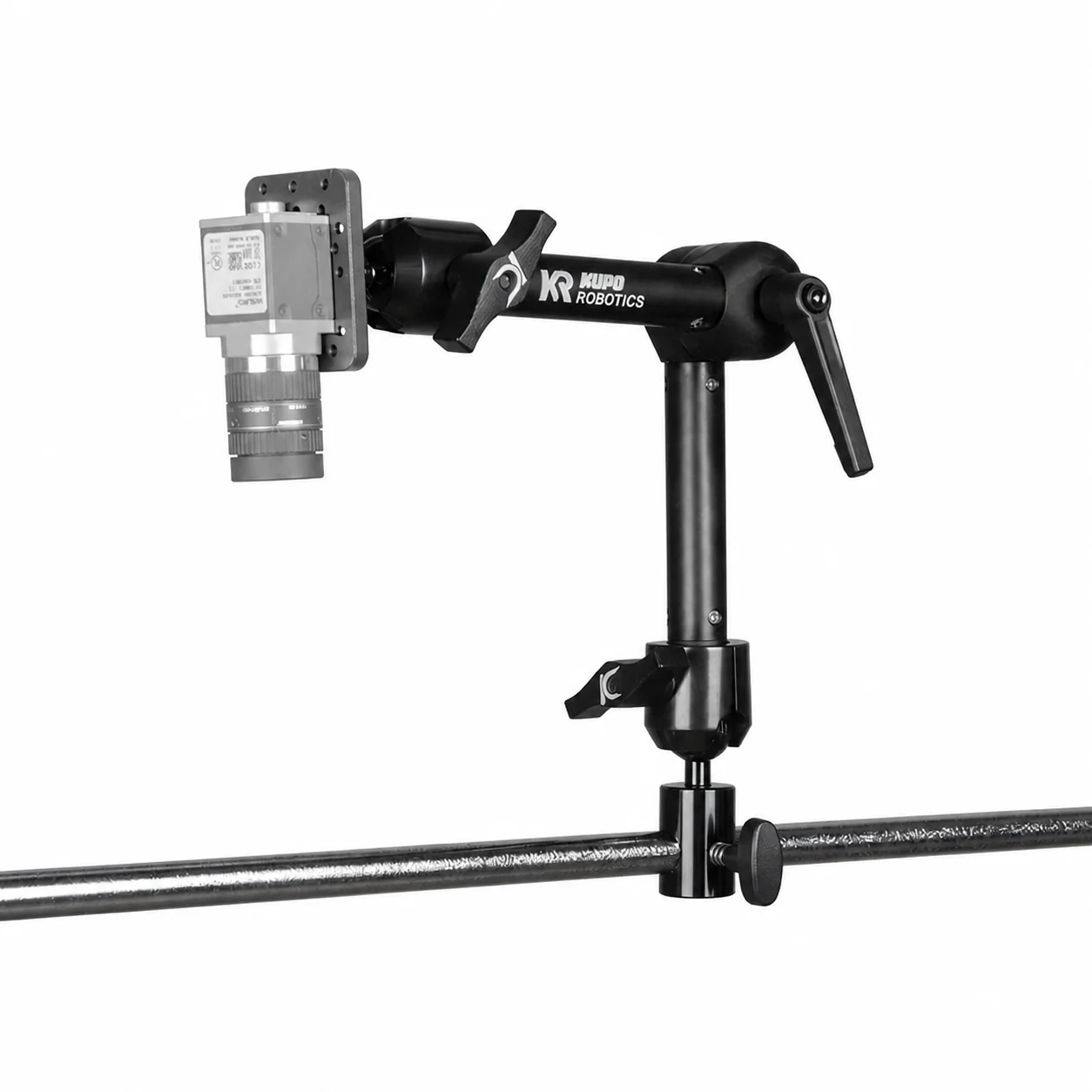
Image stability depends on the complete setup, including reach, payload center of gravity, adapter stiffness, frame placement, and cable pull.
| Check | Why it matters | Practical response |
|---|---|---|
| Camera orientation | A single 1/4"-20 screw may allow rotation. | Use a camera-specific plate or anti-rotation feature when image orientation must hold. |
| Reach | Longer arms add leverage. | Move the frame closer before choosing a longer arm. |
| Cable pull | Connector stiffness can drag the camera or light. | Add strain relief near the device. |
| Production use | A successful bench image does not validate a factory fixture. | Transfer the proven geometry to an extrusion or reviewed Factory Line path. |
A useful first configuration needs the sample envelope, camera and light models, desired working distance, and any device-specific mounting pattern.
Overall size, inspection face, loading direction, and any fixture already selected.
Body dimensions, complete mass, connector exit, thread or hole pattern, and target working distance.
Ring-light diameter or bar-light section, cable exit, and the angle being tested.